![[Note]](images/community/docbook/note.png) |
Note |
|---|---|
|
Geocoding repositories are made up of a group of files with .ugc.mdi file extensions. The entry point for selecting a repository is the file with a ugc.mdi extension, but it is vital that all .ugc.xxi files making up the repository are present in the same directory, and that they have the same name (before the file extension). |
![[Important]](images/community/docbook/important.png) |
Important |
|---|---|
|
In Geoconcept Web 2021 and later versions, a new file format is used for geocoding. Geocoding files created in the former file formats are no longer compatible. |
To build the reference tables used by the geocoder, you will need to submit a request by sending an email to adv@geoconcept.com: a serial number will be returned to you that will allow you to update Universal Geocoder via the Licence activation menu in Geoconcept 2021 and later versions. When using an earlier version of Geoconcept Web and Geoconcept, specify this in your message.
The construction of a referencial geocoding takes place in two separate steps from the Geoconcept GIS application:
- In the first instance, three text files are generated, CITIES.txt, STREETS.txt and LINKS.txt using the Generate reference files button;
- Then, from the files generated in the first step, the Generate reference table button compiles the associated referencial geocoding (.ugc.xxi) so it is ready to be used for your geocoding operations.
To generate the CITIES.txt, STREETS.txt and LINKS.Ttxt files, the command to use in Geoconcept is Generate reference files in the Data/Geocoder menu and the UGC Builder pane.
The reference table is the hingepin of the geocoding system. It is constructed on a geographic database, and is its mirror. The more exhaustive the geographic base, the more dense and complete is the reference table, and the more efficient is the geocoding, with high rates of success.
The map integrating all the cartographic data necessary to the constitution of geocoding files must be constructed. It is essential that it contains all the postal data needed to obtain good geocoding results. The data to geocode must fulfil the needs of the geocoding operation.
The main encompassing, or encircling entities for the map (often in France these are town objects) must have a zone code (in France this will often be the postcode).
![[Warning]](images/community/docbook/warning.png) |
Warning |
|---|---|
|
It is impossible to geocode addresses on street number using a reference table generated from a geographic database with streets that are not numbered and that do not have exhaustive data in a dense urban milieu. The geocoding engine can only work with the data it is supplied with, so if problems occur, the first thing to examine is the cartographic data that has served to created the reference table. |
The first step is to select level 1 objects, that is the encircling entities that are (in France anyway) generally speaking, towns or regions.
The Search command in the Data/Queries menu in Geoconcept serves to search and select encompassing entities on the map, for example, Administrative unit, Town.
Once the selection has been applied, it will then be possible to set the parameters for generating the text files.
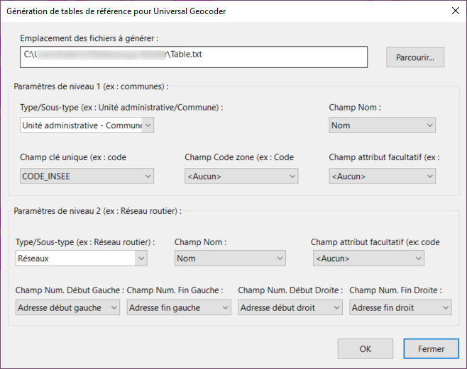
Select Generate reference files in the Data/Geocoder menu to set the parameters as required.
The configuration is made up of the three following steps.
Define the disk location for the files once they have been generated, as well as the associated filenames Click on Browse, and then indicate the storage filepath for the two files to generate. Don’t forget to indicate the name to associate to the file generation, this name being most often that of the encircling entity selected (in France, this would be the town).
Files generated will have the specified name with a suffix as follows: _CITIES.txt, _STREETS.txt, _LINKS.txt and _METADATA.xml.
Configure the items necessary to supply the level 1 items The term level 1 qualifies the objects encircling those of level 2, the streets. Generally speaking, level 1 corresponds to the towns or localities.
Six fields, of which one is optional, must be defined:
- Class / Subclass: the Geoconcept field linked to the level 1 encircling entity. The Subclass is not compulsory;
- Name: the name of this entity that must appear in the reference table that serves to execute the geocoding operations. Generally speaking, the global Name field is used.
For HERE data, we would associate this for example to Administrative unit – Town.
- Unique key field: this field should allow characterisation in a general way of each of the level 1 objects. We therefore take, in the case of France, the INSEE code, that provides a unique identifier for each town;
- Post code field: this field also provides information about the map objects. In France, this corresponds to the Post Code. We can associate to this field any other field that can be used as a geocoding key, since it represents a postal data item. But we could also associate to it a field that could serve as a discriminator (or condition) to permit distinction between two entities of the same name (for example: the number of the Department in France).
- Attribute field: this optional field supplies additional information about level 1 objects.
![[Warning]](images/community/docbook/warning.png) |
Warning |
|---|---|
|
It is vital that the Unique key field contains a unique identifier for each level 1 object. If, in the map, the INSEE code (if we are working on France for example) is not present, a Counter field can be created to serve as unique key on the objects. Sometimes it can be simpler to just use the Geoconcept identifier. |
Configure the items necessary to supply the level 1 items These level 2 objects are included in the group represented by those at level 1. Generally speaking, these level 2 objects correspond to the road network, which is a line type structure.
Seven items, one of which is optional, must be defined:
- Class / Subclass: the Geoconcept Class linked to the level 2 entity. Usually, this will be a Road network Class. The Subclass is not compulsory;
- Attribute: this field is optional, and provides additional information about level 2 objects. It can, for example, be linked to the IRIS code or the Street block code associated to streets;
![[Warning]](images/community/docbook/warning.png) |
Warning |
|---|---|
|
This Attribute field associated to streets can sometimes be useful. Above all, it is of interest when retrieved at the end of a geocoding operation, for example to retrieve IRIS codes. |
- Name: the name of the street that must appear in the reference table and that serves to perform geocoding operations. Usually, we use the Name global field;
![[Warning]](images/community/docbook/warning.png) |
Warning |
|---|---|
|
It is vital for streets that the name contains the complete label, that is, both the type of street (for example: street) and the street name (for example: Monge). |
Four fields are linked to the street numbers:
- Num End Left: the last number on the street section, even or odd, taking into account the street number;
- Num Start Left: the first number on the street section, even or odd, taking into account the street number;
- Num End Right: the last number on the street section, even or odd, taking into account the street number;
- Num Start Right: the first number on the street section, even or odd, taking into account the street number.
Generating files by administrative entity If the user wishes to create a reference table that only contains encircling polygons (French towns, for example), the user should not fill in any information for level 3 objects. The STREETS.txt file will therefore remain empty.
When the CITIES.txt and STREETS.txt text files are generated, it will suffice not to have assigned any parameters for the level 2 elements. The STREETS.txt file generated will therefore be empty.
![[Warning]](images/community/docbook/warning.png) |
Warning |
|---|---|
|
The objects designated as encircling objects to geocode can just as well be polygon type objects as points. |
Generating files with a reference point and not a line When generating a reference table using point addresses, follow the identical procedure as that described above for generating the files, indicating the same field for the four street number fields.
The first text file (CITIES.txt) contains all the information necessary to all localities concerned (encircling objects) for the geographic space to which the geocoding is to be applied.
The file contains five columns, that must remain in the prescribed order:
- Town name: contains the name of the town or locality containing the address;
- Area code: code characterising the locality (in France this would be the post code for the town);
- Unique key: key describing each town in a unique way (in France, this would be the INSEE code for the town);
- Attribute: any code that serves to provide additional information;
- X in WGS 84;
- Y in WGS 84.
![[Warning]](images/community/docbook/warning.png) |
Warning |
|---|---|
|
The X and Y coordinates represent the centroid of the town in the case of a polygon object or its coordinates if it is a point object. They are expressed in the WGS 84 projection system. |
In the event that there might exist different names that could characterise the polygon entity (notably to handle a bilingual scenario) it is possible to store all these names in the reference table. The Town name field must be filled with all possible names, concatenated using the @ character.
For example, for the polygon entity Paris, the town name Paris@Parigi. This new town name must appear both in the CITIES.txt file, in the STREETS.txt file, and if necessary in the LINKS.txt file.
The second text file (STREETS.txt) contains all the information indispensable to all the streets in the geographic space to which the geocoding operation is to be applied.
The file must contain nine columns, in a particular order:
- Street name: contains the road section name;
- Street attribute: any code that serves as an additional attribute (for example: the identifier for the street section, the IRIS code);
- Num End Left: the last number in the street section, even or odd, taking into account the street number;
- Num Start Left: the first number on the street section, even or odd, taking into account the street number;
- Num End Right: the last number on the street section, even or odd, taking into account the street number;
- Num Start Right: the first number on the street section, even or odd, taking into account the street number;
- Town name: contains the name of the town or locality containing the address;
- Town attribute: any code that serves as additional information on the encircling entity;
- Unique key for the town: key describing the town in a unique way (in France, this would be the INSEE code for the town).
There follows a series of columns, without names, characterising the geometry of the street:
- X1 : the start abscissa for the street section;
- Y1 : the start ordinate for the street section;
- X2 : the end abscissa for the street section;
- Y2 : the end ordinate for the street section;
- the number of intermediate points making up the street section;
- a series of pairs of coordinates that express, for each column, the delta X and delta Y for each intermediate point.
![[Warning]](images/community/docbook/warning.png) |
Warning |
|---|---|
|
It is vital to verify in the two text files, the pairs entitled Name of the encircling entity and Associated Unique key. These should be identical. |
In the case of a geocoding operation from a reference point, the geometry associated to each section is of the type: X1 Y1 X1 Y1 0. In effect, as the street section is represented by a point, only the coordinates of this point are recorded.
This file allowing you to generate hierarchies, is required, and is supplied empty, except for the header titles in 3 columns
- Parent;
- Parent;
- Class.
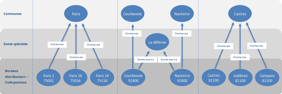
The file of level 1 hierarchies (optional), that enables creation of hierarchical links between administrative polygon entities. This facilitates the address search function. This functionality is reserved for users with a high level of competence in the field of geocoding.
The text file takes the following form (example of Paris and its districts):
|
Parent |
Child |
Type |
Parent name |
Child name |
Child postcode |
|
4981324_City |
4981324 |
Contains |
PARIS |
1st ARRONDISSEMENT |
75001 |
|
4981324_City |
4981286 |
Contains |
PARIS |
10th ARRONDISSEMENT |
75010 |
|
4981324_City |
4981290 |
Contains |
PARIS |
11th ARRONDISSEMENT |
75011 |
|
4981324_City |
4981294 |
Contains |
PARIS |
12th ARRONDISSEMENT |
75012 |
|
4981324_City |
4981298 |
Contains |
PARIS |
13th ARRONDISSEMENT |
75013 |
|
4981324_City |
4981302 |
Contains |
PARIS |
14th ARRONDISSEMENT |
75014 |
|
4981324_City |
4981306 |
Contains |
PARIS |
15th ARRONDISSEMENT |
75015 |
|
4981324_City |
4981312 |
Contains |
PARIS |
16th ARRONDISSEMENT |
75116 |
|
4981324_City |
4981310 |
Contains |
PARIS |
16th ARRONDISSEMENT |
75016 |
|
4981324_City |
4981314 |
Contains |
PARIS |
17th ARRONDISSEMENT |
75017 |
|
4981324_City |
4981316 |
Contains |
PARIS |
18th ARRONDISSEMENT |
75018 |
|
4981324_City |
4981318 |
Contains |
PARIS |
19th ARRONDISSEMENT |
75019 |
|
4981324_City |
4981332 |
Contains |
PARIS |
2nd ARRONDISSEMENT |
75002 |
|
4981324_City |
4981326 |
Contains |
PARIS |
20th ARRONDISSEMENT |
75020 |
|
4981324_City |
4981338 |
Contains |
PARIS |
3rd ARRONDISSEMENT |
75003 |
|
4981324_City |
4981344 |
Contains |
PARIS |
4th ARRONDISSEMENT |
75004 |
|
4981324_City |
4981350 |
Contains |
PARIS |
5th ARRONDISSEMENT |
75005 |
|
4981324_City |
4981356 |
Contains |
PARIS |
6th ARRONDISSEMENT |
75006 |
|
4981324_City |
4981362 |
Contains |
PARIS |
7th ARRONDISSEMENT |
75007 |
|
4981324_City |
4981368 |
Contains |
PARIS |
8th ARRONDISSEMENT |
75008 |
|
4981324_City |
4981374 |
Contains |
PARIS |
9th ARRONDISSEMENT |
75009 |
Where:
- Parent: Identifier of the parent entity (ex Paris) located in the file CITIES.txt;
- Child: Identifier of the child entity (Ex: an arrondissement or district for Paris) located in the CITIES.txt file;
- Type: types of link (contains, intersects);
- • Parent name (optional): name of parent entity;
- • Child name (optional): name of child entity;
- • Child postcode (optional): post code of the child entity.
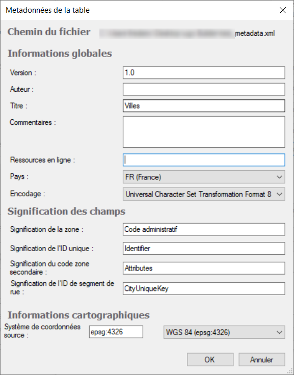
The metadata file is required, and does not normally require editing, however if necessary the user can adapt it using the Edit button in the Reference table generation window (cf. the next paragraph).
The following information items can be edited via the editing interface:
- Filepath;
- Version;
- Author;
- Title;
- Comment;
- On-line resources;
- Country;
- Coding;
- Description of the zone entity: defines what the reference zone (for example, the post code) corresponds to;
- Description of the Unique ID entity: defines what the unique identifier in the table corresponds to;
- Description of the secondary area code: defines what the (secondary) reference zone corresponds to (the INSEE code, for example);
- Description of the road segment ID;
- Source coordinates system;
- Output coordinates system.
The last step is to generate the files making up the geocoding repository with .ugc.xxi file extensions, to calculate the X and Y coordinates and associate them to addresses, from generated files containing the relevant geographic and identifier information.
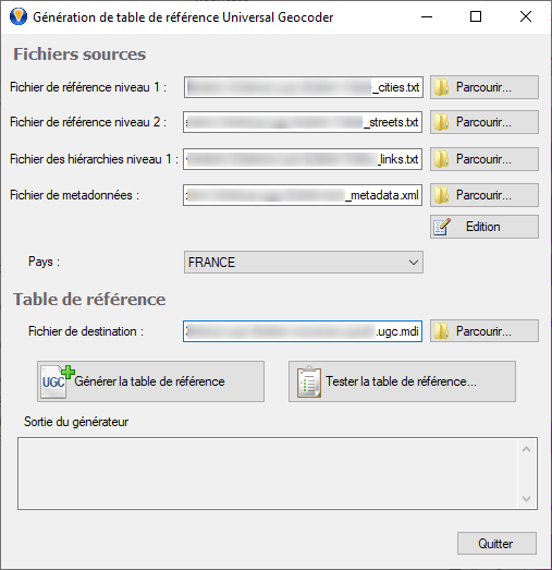
The Generate a reference table module is available in Geoconcept’s Data/UGC Builder Pane menu option.
In this dialogue the user defines the text files from which the table will be created:
- the level 1 file (CITIES.txt) contains information encircling level 2 information (in France, this will be the towns);
- the level 2 file (STREETS.txt) contains information concerning all roads and thoroughfares, supporting the address information.
- the hierarchies file (LINKS.txt) contains information about relationships between polygon entities;
- the metadata file (METADATA.xml) contains information used to generate the table.
Before generating the repository, you will need to specify the destination file, by indicating the filepath and .ugc.mdi filename before validating.
The Generate reference table button allows you to create a reference table that incorporates the parameters entered previously.
The integrity of the reference file generated can also be verified using the Test reference table button.
The user must define the reference language used by the grammar file.
- Disk location of the table to verify;
- Disk location of the associated grammar file;
- Generate statistics and/or Geocode the table by checking the appropriate options.
This last option enables detection of any inconsistencies in geocoding each of the present addresses.
- Disk location of the journal file containing the result of the verification.
Once the files have been created, the procedure to follow requires definition of:
- • the filepath to the file CITIES.txt containing the encircling entities or localities (in France, these would be towns);
- for the level 2 file, the filepath to the empty file generated called STREETS.txt;
- the hierarchies file (LINKS.txt);
- the metadata file (METADATA.xml).
A reference table with only level 1 entities is then created.


